From Hover to Cruise: Investigating PID Control for a Hybrid VTOL Aircraft
Core Theme: Avionics, Control Systems & Robotics
Introduction: Why Hybrid VTOL Aircraft?
When I think about the future of aviation, one of the concepts that interests me the most is the Hybrid Vertical Take-Off and Landing (VTOL) aircraft.
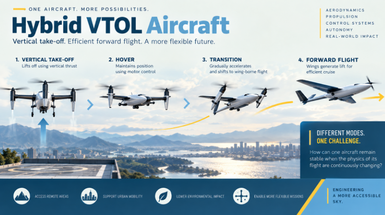
Imagine an aircraft that can take off vertically from a small area like a helicopter and then transition into efficient forward flight like a conventional aeroplane. This combination makes Hybrid VTOL aircraft particularly interesting because it brings together characteristics of rotary-wing and fixed-wing flight.
During take-off and landing, a Hybrid VTOL can use its vertical propulsion system to operate without a conventional runway. Once airborne, it can transition into forward flight, where its wings contribute increasingly to lift. Flight-control systems must therefore manage different operating conditions as the aircraft moves between VTOL and fixed-wing modes.[6][9]
As a student interested in aerospace engineering, I find this concept fascinating because it brings together several areas of engineering: aerodynamics, propulsion, electronics, sensors, programming and control systems.
However, while learning more about these aircraft, I realised that designing the physical structure of a VTOL is only one part of the challenge.
Another major challenge is making sure that the aircraft remains stable and controllable throughout its flight.
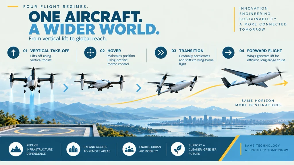
A Hybrid VTOL can pass through several different flight conditions:
- Vertical Take-Off
- Hover
- Transition
- Forward Flight
The forces and control requirements can change significantly between these stages.[1][6]
This led me to one of the most interesting parts of VTOL technology: flight control.
In this article, I explore my understanding of how PID control can contribute to the stabilization and control of a Hybrid VTOL aircraft. I focus on feedback control, the proportional, integral and derivative terms, controller tuning, control allocation, and the additional challenge created by the transition between hovering and forward flight.
Contents
- 1. Understanding the Flight-Control Challenge
- 2. What Does a Flight-Control System Do?
- 3. Understanding Feedback Control
- 4. What Is a PID Controller?
- 5. What Does Kp Actually Do?
- 6. What Does Ki Add?
- 7. What Does Kd Add?
- 8. My Control-System Model
- 9. My Approach to PID Tuning
- 10. The Experiment I Would Use to Evaluate the Controller
- 11. What Can Go Wrong?
- 12. The Problem Gets Harder During VTOL Transition
- 13. Gain Scheduling
- 14. Simulation Before Flight Testing
- 15. Tools and Systems That Inspired My Learning
- 16. What I Learned
- 17. Questions I Want to Explore Next
- 18. From Learning to Engineering
- Inspiration & References
1. Understanding the Flight-Control Challenge
Before understanding PID controllers, I believe it is important to understand why controlling a Hybrid VTOL aircraft can be challenging.
Unlike a conventional fixed-wing aircraft operating mainly in forward flight, a Hybrid VTOL has to operate across multiple flight regimes.
The flight may begin with vertical take-off. During this stage, the aircraft depends primarily on vertical propulsion to generate sufficient thrust to support its weight.
After take-off, the aircraft may enter a hovering phase, where it needs to maintain a stable attitude and, depending on the control mode, its position.
Although hovering may appear simple from the outside, maintaining stability requires continuous correction. Small disturbances can change the aircraft’s attitude or position, requiring the flight controller to respond.
The next stage is the transition phase, which I find particularly interesting.
During transition, the aircraft begins moving forward and gradually changes from primarily VTOL behaviour toward fixed-wing flight. PX4 documentation describes VTOL controllers as combining multicopter and fixed-wing control structures, with specific logic for the transition between them.[5][6]
As the aircraft gains speed, aerodynamic forces become increasingly important. The relationship between propulsion, lift, drag and control-surface effectiveness changes with the flight condition.[1][5]
Finally, the aircraft enters forward or cruise flight, where the wings provide most of the aerodynamic lift.
The important thing I realised while learning about these stages is that the aircraft does not behave in exactly the same way throughout the flight.
A controller that performs well during hover may not automatically provide the same response during transition or forward flight.
This is one of the reasons why flight control is such an interesting engineering problem.
2. What Does a Flight-Control System Do?
In simple terms, a flight-control system helps the aircraft determine what it is doing and make corrections when necessary.
For example, imagine that an aircraft is supposed to maintain a level attitude. A disturbance causes it to roll to one side.
The aircraft’s sensors detect changes in its motion and attitude. The flight-control system processes this information and generates commands intended to reduce the error. Modern autopilot systems can use measurements from sensors such as gyroscopes, accelerometers, magnetometers, barometers, GPS/GNSS and, where available, airspeed sensors.[3]
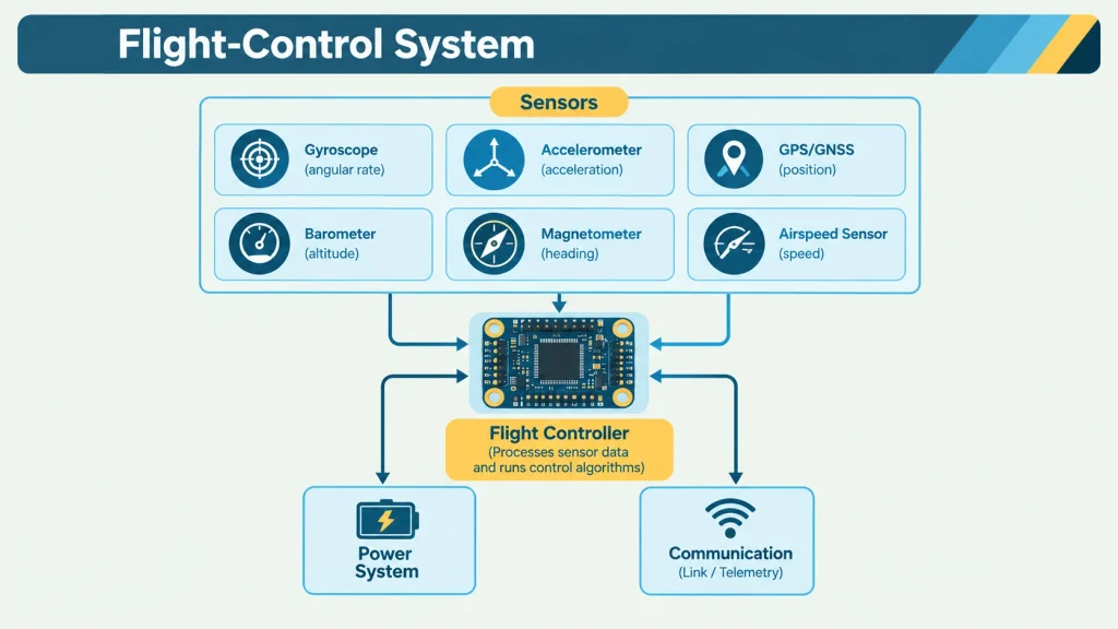
Some flight-control architectures also use state-estimation systems to combine sensor information and estimate quantities such as attitude, heading, position and velocity.[4]
The process can be simplified as:
- Desired State
- Measure Actual State
- Calculate Error
- Correct
- Measure Again
The basic definition of error is:
Error = Desired Value − Actual Value
This simple relationship became important to my understanding of control systems because the controller does not simply issue a command once.
It continuously compares what the aircraft should be doing with what the aircraft is actually doing.
That creates a feedback system.
3. Understanding Feedback Control
Feedback control is one of the fundamental ideas behind automated flight control.
Suppose I want an aircraft to maintain a pitch angle of zero degrees.
If a disturbance causes the aircraft to pitch upward, the sensors detect the change. The controller compares the measured pitch with the desired pitch and calculates the error. It then generates a corrective command. The aircraft responds. The sensors measure the new state again. The process repeats.
This creates a continuous feedback loop:
- Desired State
- Error
- Controller
- Control Allocation
- Actuators
- Aircraft
- Sensors
- Feedback

This type of control architecture is reflected in practical flight-control systems. PX4, for example, uses cascaded control structures and PID-based controllers within its flight-control architecture.[5]
Depending on the aircraft, actuators can include:
- Electric motors
- Propellers
- Electronic Speed Controllers (ESCs)
- Elevons
- Elevators
- Rudders
- Other aerodynamic control surfaces
The interesting question for me was:
How does the controller decide how much correction to apply?
This is where PID control becomes useful.
4. What Is a PID Controller?
PID stands for:
- P — Proportional
- I — Integral
- D — Derivative
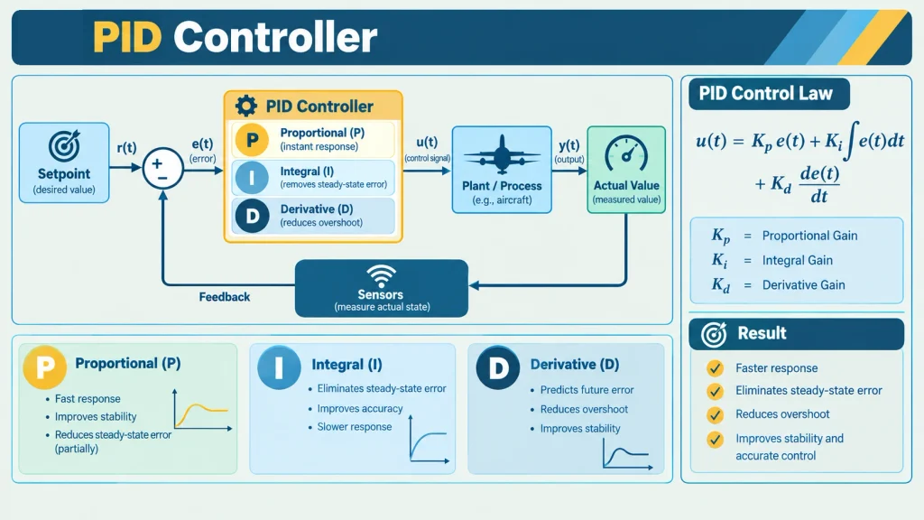
A PID controller is a feedback-control method used in many control applications, including flight-control systems. The fundamental idea is to use the error between a desired state and the measured state to calculate a corrective control action.[2][5][8]
The three main controller parameters are:
- Kp — Proportional Gain
- Ki — Integral Gain
- Kd — Derivative Gain
A simplified mathematical representation is:
At first, this equation looked complicated to me.
However, once I separated it into three parts, I found it much easier to understand.
Each component asks a slightly different question about the error:
P-How large is the error right now?
I-How much error has accumulated over time?
D-How quickly is the error changing?
NASA’s flight-control material describes these three terms in terms of present error, accumulated error and the rate of change of error.[2]
5. What Does Kp Actually Do?
The proportional component responds to the current error.
If the aircraft is far away from its desired condition, the proportional component produces a larger corrective response.
For example, if the aircraft tilts significantly to one side, the proportional controller attempts to generate a correction proportional to the size of the error.
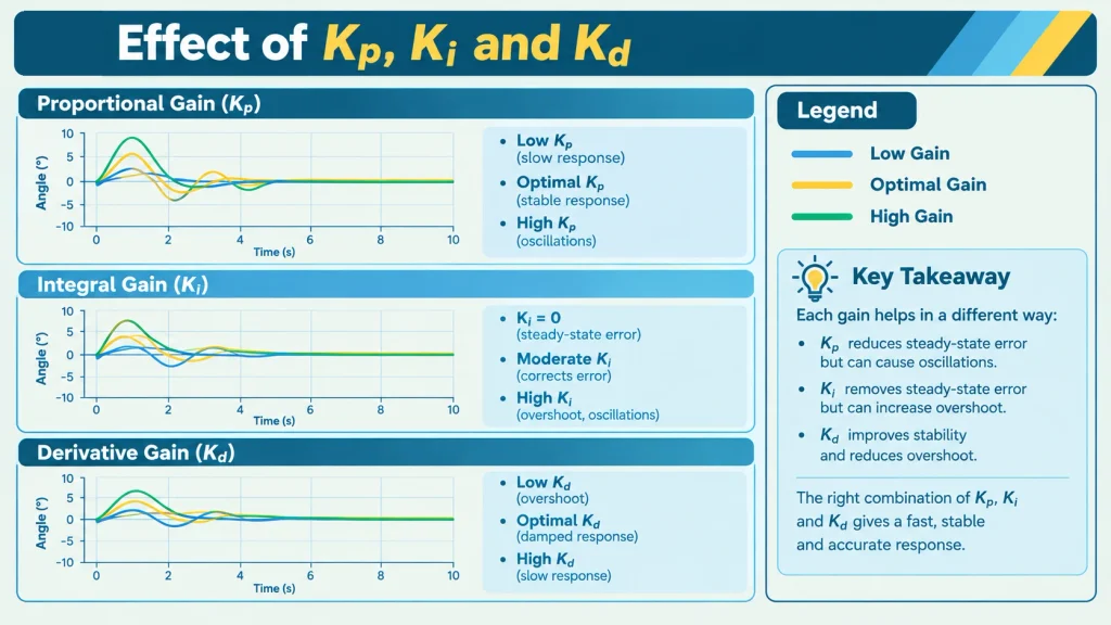
Increasing Kp generally makes the controller respond more strongly to errors.
However, while learning about PID control, I found that higher is not always better.
If Kp becomes too high, the system can respond too aggressively and begin oscillating around the desired state. If Kp is too low, the response may be slow.
This creates a fundamental tuning problem:
How much correction is enough without causing excessive oscillation?
Practical autopilot documentation also describes the relationship between controller gains and vehicle response, including the need to tune the controller for the specific aircraft.[8][10]
6. What Does Ki Add?
The integral component considers the error accumulated over time.
Sometimes a proportional controller may reduce an error without completely eliminating a persistent offset.
For example, an aircraft might remain slightly away from its desired condition even though the proportional controller is continuously trying to correct it.
The integral term accumulates this remaining error and can increase the corrective action over time.
However, Ki must also be used carefully.
If too much integral action accumulates, the controller can experience integral windup.
In practical control systems, limits or anti-windup mechanisms can be used to prevent the integral component from becoming excessively large. PX4 documentation, for example, describes limiting integral authority to prevent windup.[5]
This was one of the first places where I began to understand that a theoretical control equation and a real flight controller are not exactly the same thing.
The equation is only the beginning.
The practical implementation has to deal with real sensors, real actuators and real physical limitations.
7. What Does Kd Add?
The derivative component considers how quickly the error is changing.
I think of it as asking:
Is the aircraft moving toward the desired condition too quickly?
For example, if an aircraft is already moving rapidly toward its desired attitude, derivative action can help provide damping and reduce excessive overshoot.
This makes the derivative term particularly interesting because it is not only concerned with the current error. It also responds to the rate of change of that error.[2]
However, derivative control has another challenge.
Sensors are not perfectly clean.
Aircraft can experience vibration, measurement noise and rapidly changing signals. Because the derivative term responds strongly to changes in the signal, noise can produce unwanted corrections.
Practical flight-control systems therefore commonly use filtering on derivative-related signals. PX4’s controller documentation, for example, describes low-pass filtering on the derivative path to reduce noise.[5]
This helped me understand why flight-control engineering involves much more than simply calculating three gains.
8. My Control-System Model
After studying feedback control and existing flight-control architectures, I developed a simplified mental model for how I would think about a PID-controlled VTOL system.
My simplified architecture
- Desired State
- Error Calculation
- PID Controller
- Control Allocation / Mixing
- Actuators
- Hybrid VTOL Aircraft
- Sensors
- State Estimation
- Feedback
The important distinction I learned here is that the PID controller does not directly “fly” the aircraft.
The controller generates a control response.
That response then has to be translated into commands that the aircraft’s actuators can actually execute.
This process is often described as control allocation or, in simpler systems, mixing.
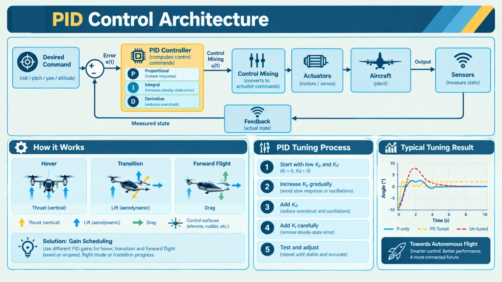
PX4 documentation describes control allocation as the stage that converts desired force and torque commands into actuator commands according to the aircraft configuration.[6]
For a Hybrid VTOL, this becomes especially interesting because the relevant actuators can change in importance between flight regimes.
During hover, differential motor thrust can play a major role.
During forward flight, aerodynamic control surfaces can become increasingly important.
During transition, both forms of control may interact.
9. My Approach to PID Tuning
Writing the PID equation is relatively straightforward.
Finding suitable values for Kp, Ki and Kd is much harder.
This process is called PID tuning.
A poorly tuned controller can result in:
- Slow response
- Excessive oscillations
- Overshoot
- Poor disturbance rejection
- Unwanted actuator behaviour
Professional autopilot documentation describes systematic tuning processes rather than assuming that one set of gains will work for every vehicle. ArduPilot, for example, separates tuning of different control loops and also highlights the importance of filtering and aircraft-specific setup.[8][10]
My simplified learning approach is:
- Begin with low Ki and Kd.
- Gradually increase Kp.
- Observe the response.
- Identify excessive oscillation or slow response.
- Introduce Kd to provide damping.
- Introduce Ki carefully to reduce persistent error.
- Repeat the process.
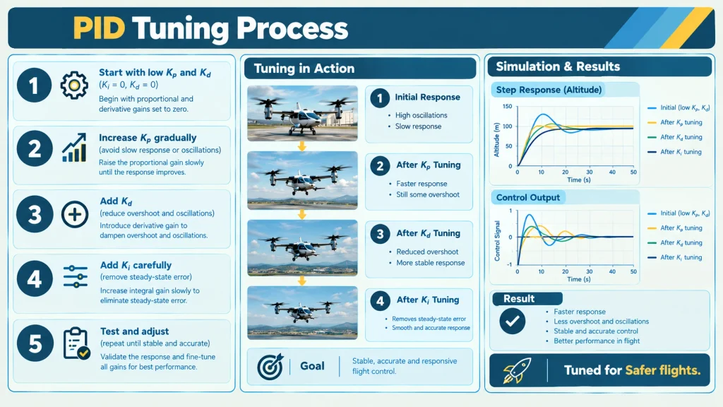
This is not a universal tuning recipe.
Instead, it is the framework I use to understand the logic behind tuning.
The actual values would depend on the aircraft.
Factors such as mass, propulsion characteristics, moments of inertia, aerodynamic design and centre of gravity can all affect the response of the system.
This led me to an important engineering principle:
There is no single set of PID values that can simply be copied from one aircraft to another and expected to work perfectly.
10. The Experiment I Would Use to Evaluate the Controller
The next step in turning this topic from something I learned into an engineering investigation would be to test the controller systematically.
I would begin with a controlled simulation or test environment.
For each tuning trial, I would record:
- Kp
- Ki
- Kd
- Desired response
- Measured response
- Rise time
- Overshoot
- Settling behaviour
- Steady-state error
- Oscillation
- Control effort
11. What Can Go Wrong?
One of the reasons I became more interested in control systems was that making a controller work is not simply a matter of making the aircraft respond.
The response also needs to be appropriate.
Possible problems include:
- Too little control response
- Excessive oscillation
- Overshoot
- Integral windup
- Sensor noise
- Vibration
- Actuator saturation
- Poorly calibrated sensors
- Incorrect assumptions about the aircraft model
Practical autopilot documentation highlights several of these issues. PX4 describes integral limits and derivative filtering, while ArduPilot’s tuning documentation discusses the importance of vibration filtering and appropriate aircraft setup before tuning.[5][8][10]
This made me realise that a controller is part of a larger system.
The performance of the controller depends not only on the mathematical equation but also on the aircraft, sensors, actuators and software surrounding it.
12. The Problem Gets Harder During VTOL Transition
The transition from hovering to forward flight is the part of the problem that interests me most.
During hover, the aircraft depends heavily on its vertical propulsion system for stability and control.
As it accelerates, the wings begin producing more aerodynamic lift and the effectiveness of aerodynamic control surfaces changes.
At the same time, the aircraft’s propulsion and control requirements are changing.
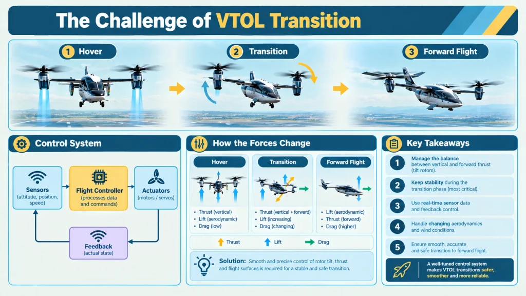
PX4 describes VTOL control as combining multicopter and fixed-wing controllers, with specific logic used during transition.[5]
PX4’s VTOL configuration documentation also treats transition as a separate condition that requires its own consideration rather than simply treating the aircraft as two completely independent modes.[6]
ArduPilot similarly describes QuadPlane transition as the process of changing between primarily VTOL/copter-like flight and conventional fixed-wing flight.[9]
This made me think about an important question:
If the aircraft itself is changing its behaviour, should the controller remain exactly the same?
That question led me to gain scheduling.
13. Gain Scheduling
One possible approach to changing flight conditions is gain scheduling.
The basic idea is that controller parameters can be adjusted according to the operating condition.
For example, a Hybrid VTOL could potentially use:
- One set of gains during hover
- Another set during transition
- Different gains during forward flight
The scheduling variable could be related to factors such as airspeed or flight mode.
PX4 documentation specifically discusses the relationship between controller behaviour and airspeed and describes airspeed scaling within its fixed-wing control architecture.[5]
This is where the topic becomes more interesting to me.
I initially thought of PID tuning as finding three numbers:
Kp + Ki + Kd
But I now see that a more advanced system may involve asking:
- Which controller should be active?
- Which gains should be used?
- When should they change?
- How should the transition between controllers happen?
This moves the problem from simple PID tuning toward broader questions in adaptive and model-based control.
14. Simulation Before Flight Testing
Before testing a new flight-control system on a physical aircraft, simulation can provide a controlled environment for exploring its behaviour.
A simplified mathematical model could include variables such as:
- Aircraft mass
- Centre of gravity
- Moments of inertia
- Motor thrust
- Aerodynamic characteristics
- Control-surface response
The controller could then be tested under different conditions.
For example:
- Disturbances
- Sensor noise
- Different initial conditions
- Different PID gains
- Changing airspeed
- Different transition conditions
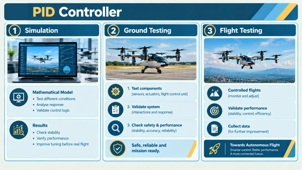
Simulation is particularly interesting to me because it allows one variable to be changed while observing how the system responds.
It also provides a way to identify potential problems before moving to physical testing.
The general engineering principle I take from this is:
Test, observe, understand, then modify.
The aim is not simply to make the aircraft fly.
It is to understand why the aircraft responds in a particular way.
15. Tools and Systems That Inspired My Learning
Two open flight-control ecosystems that helped me understand these concepts were PX4 Autopilot and ArduPilot.
Studying their documentation helped me connect the theoretical concepts I was learning with practical flight-controller architecture.
PX4’s documentation was particularly useful for understanding:
- Sensor inputs
- State estimation
- Cascaded control
- PID-based controllers
- Control allocation
- VTOL flight modes
- Transition logic
- Airspeed-related control behaviour
- Controller tuning[3][4][5][6][7]
ArduPilot’s documentation helped me understand:
- QuadPlane VTOL control
- Roll, pitch and yaw tuning
- Filtering
- Transition behaviour
- Manual tuning
- Automated tuning[8][9][10]
I did not use these systems as a source from which to copy an existing controller.
Instead, I used their technical documentation as a way to understand how the concepts I was studying can appear in real flight-control systems.
16. What I Learned
The biggest lesson I took from this exploration is that engineering is not simply about finding an answer.
It is about asking a useful question, building a model, testing an idea, observing what happens, understanding why it happened, and then asking a better question.
When I started learning about PID controllers, I thought the main challenge was understanding the equation.
Now I think the equation is only the beginning.
A practical flight-control problem involves:
- Aircraft Dynamics
- Sensors
- State Estimation
- Controller
- Actuators
- Software
- Testing
A change in one part of the system can affect the behaviour of the others.
I also learned that the word “autonomous” should not be used too loosely.
A PID controller can contribute to stabilization and control, but PID control by itself does not make an aircraft fully autonomous.
Autonomous flight involves additional systems for sensing, estimation, guidance, navigation, decision-making and control.
Understanding this distinction helped me think more carefully about how complex aerospace systems are actually constructed.
17. Questions I Want to Explore Next
This project has answered some of my questions, but it has created even more.
Some of the questions I would like to investigate next are:
1. Can PID gains be automatically adapted?
Instead of manually selecting gains, could the controller estimate the aircraft’s current condition and adapt its parameters?
2. How should the controller behave during transition?
Could the transition between hover and fixed-wing control be made smoother by continuously blending different control strategies?
3. How can sensor noise be reduced?
How much does IMU noise or vibration affect PID performance?
4. How can simulation be made more realistic?
A simulation model is only useful if it represents important characteristics of the real aircraft accurately.
5. When should PID be replaced by a more advanced control strategy?
This leads toward subjects such as:
- Adaptive control
- Model Predictive Control
- State-space control
- Nonlinear control
- Robust control
- Reinforcement learning
These are areas I would like to explore as I develop my understanding of aerospace engineering.
18. From Learning to Engineering
This project began with a simple question:
How can an aircraft remain stable when its flight behaviour is continuously changing?
I initially approached the problem through PID control because it provided a relatively understandable mathematical framework.
But as I explored the topic, the question became much larger.
I began thinking about how sensors measure the aircraft, how those measurements are converted into an estimate of its state, how the controller calculates an error, how control commands are allocated to different actuators, and how the entire process changes when the aircraft moves from hover to forward flight.
That progression changed the way I think about engineering.
I no longer see a controller simply as a piece of software containing three gains.
I see it as one component of a much larger system.
For a Hybrid VTOL aircraft, that system connects:
- Aerodynamics
- Propulsion
- Sensors
- Estimation
- Control
- Actuation
- Flight
This is what makes the subject so interesting to me.
The aircraft has to interact with a constantly changing physical environment, while the control system has to interpret measurements, calculate corrections and respond within very short time scales.
As a student interested in aerospace engineering, this exploration has shown me how mathematics, physics, programming, electronics and systems engineering can come together in a single problem.
I am still at the beginning of this learning journey.
I have not yet solved the complete control problem, and I do not expect to.
What interests me is the process of moving from a simple question to a model, from a model to an experiment, and from an experiment to a better question.
For me, that is where engineering begins.
Inspiration & References
My interest in Hybrid VTOL flight control was inspired by studying existing flight-control and autopilot systems, particularly PX4 Autopilot and ArduPilot.
The technical documentation helped me understand aircraft forces, sensors, feedback control, PID-based stabilization, control allocation, VTOL transition and tuning.
The explanations, simplified models and reflections in this article are my own learning-based interpretation of the concepts studied. The references below are provided to identify the technical sources that informed my understanding.
References
- NASA Glenn Research Center — Four Forces on an Airplane
- NASA Langley Research Center — Flight Control Fundamentals for Enabling Autonomous Systems — official NASA source.
- PX4 — Sensor Hardware & Setup
- PX4 — IMU, AHRS, and INS
- PX4 — Controller Diagrams
- PX4 — Generic Standard VTOL (QuadPlane) Configuration & Tuning
- PX4 — Auto-Tuning / VTOLThe current PX4 documentation explains autotuning for hybrid VTOL vehicles, including tuning the multicopter and fixed-wing configurations separately.
- ArduPilot — QuadPlane VTOL Tuning Overview
- ArduPilot — QuadPlane Transitions
- ArduPilot — QuadPlane Tuning Process Instructions

Bhavarth
September 26, 2026
Crazy🤩
mukund chauhan
September 27, 2026
Amazing and a very innovative Idea 💡🤓
Mukund
September 27, 2026
Amazing👍👍👍
Rishita
September 27, 2026
Well researched!!!
Manas
September 27, 2026
Good Work and Good Luck Bro